Rolivers
- 9 Posts
- 33 Comments
Everyone who has come in contact with that stuff will die.
In my universe it's not Berenstain or Berenstein....
...it's bloodstain
- Rolivers@discuss.tchncs.deto
 ·4 months ago
Hmm and i wanted to get 1 month of ultimate just to play Jedi survivor once.
- Rolivers@discuss.tchncs.deto
 ·5 months ago
Tooting my own horn. I have something to add. With the UV "Mechanic" solder mask that gets sold on Chinese webshops pre-heating the solder mask makes a HUGE difference. Apparently it contains some volatile components that interfere with the curing process.
Heating it to about 80-ish C for a few minutes and optionally letting it cool down causes the laser to almost instantly cure the mask. Any non-exposed mask will be easily washed off with some IPA.
- Rolivers@discuss.tchncs.deto
 ·7 months ago
Pearson can choke on a bag of dicks.
- Rolivers@discuss.tchncs.deto
Yes that I found as well but have/had trouble understanding why it would be built like this. Also why a MOSFET would be designed internally like this. If you want more power capability you'd get a bigger MOSFET rather than two tiny ones in parallel right?
This page helped me understand the setup. I'll post it here just for informational purpose. It took me a while to find this. https://electronics.stackexchange.com/questions/203463/dual-mosfet-8205a-lithium-battery-protection-circuit
It's related to the internal body diode of the N channel mosfet, so two of them are in series but reversed. When one MOSFET is activated, current may flow easily in one direction but be reduced by the body diode of the other. When both are activated, current may flow easily in either direction.
It seems they don't really prevent discharging or charging separately due to the body diodes but they can cut off the battery alltogether.
That's good. My switching frequency is a few times per hour.
I am a little bit concerned that the slow rise/fall time make the MOSFET go outside its operating parameters for a fraction of a second. The resistance gradually changes meaning the mosfet will dissipate more power but also less current will flow.
So if you switch many times per second the gate capacitance with the resistor acts as a low pass filter reducing the gate voltage.
That's a low bar.
Impressive and amusing.

- Rolivers@discuss.tchncs.deto
 ·9 months ago
Flat earth wasn't silly enough?
- Rolivers@discuss.tchncs.deto
Replying to myself for informational reason. Modifying voltage was more or less successful. Both optocouplers transmit a reference voltage, so both need to be adjusted simultaneously.
This can be done by changing the value of R19, a 23.2k smd resistor close to the output terminals.
I've attached a 10k pot with a 10k and 6.8k resistor in series and successfully modified the voltage down to 22.5.
The power supply itself is a piece of crap though. It claims to handle 400W but anything over 150W causes the short circuit protection to activate, never mind overheating at 150W very quickly.
Show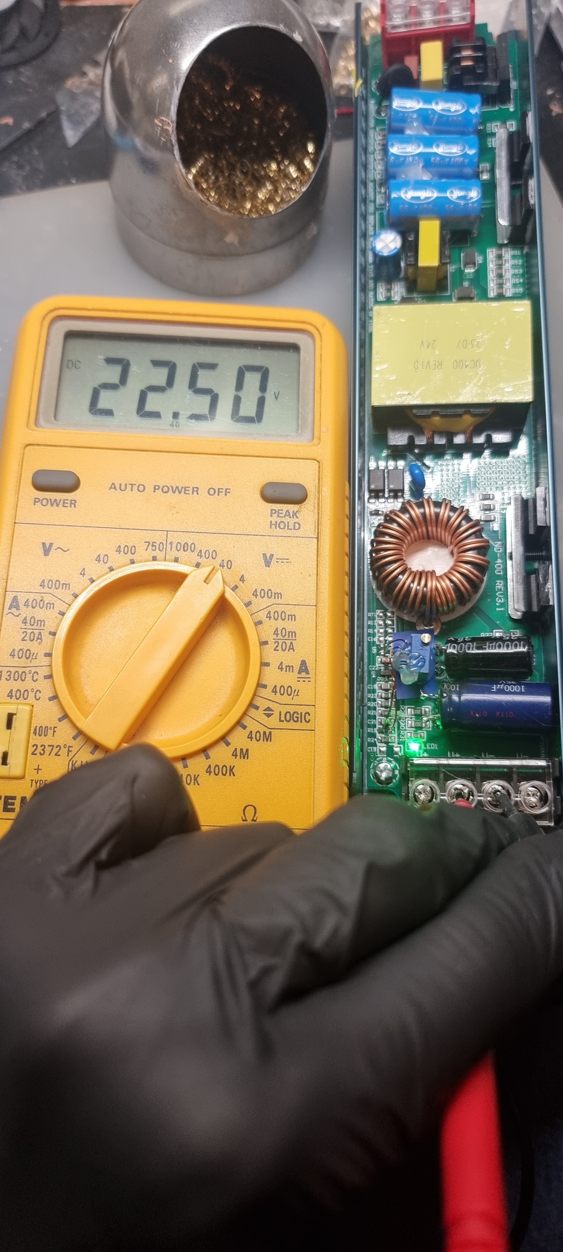
Sadlines, not deadlines. The only effect is some manager experiences mild sadness if it's not made. Nobody dies.
Xtra app from Fdroid allows ad free twitch watching.

- Rolivers@discuss.tchncs.deto
Yeah don't worry about it. Running a fan at a lower voltage than it's meant for will result in slower fan speeds and a longer lifetime. Compared to the wattage an actual laptop will draw this is absolutely nothing. I power my soldering iron with an old laptop charger without issues.
Those plugs are generally used in 12V systems but they can handle higher voltages too. It's the current you need to be mindful of for the most part, they can overheat if you try to power a space heater or something from that but a few fans won't cause any issues.
- Rolivers@discuss.tchncs.deto
 ·10 months ago
deleted by creator
- Rolivers@discuss.tchncs.deto
Where is the video? Electroboom craziness sounds entertaining.
I would rather have a buffalo take a diarrhea dump in my ear.
- Rolivers@discuss.tchncs.deto
Those 5400mWh batteries are a scam. Be very careful with them.
If the house burns down because of that your insurer will likely be difficult about it. You should also check the policy of your insurer, perhaps the cause of the fire is irrelevant.
As for fire safety. I always put my electronics in non flammable environments and make sure that everything is fused with either a current or thermal fuse.
Anything with high current consumption goes inside a metal box so that even if it does catch fire it can't take anything with it. 3D printed enclosures are fine if you mount those inside a metal bucket for example.